The obvious answer to a bending shaft is “make it bigger.” The useful engineering answer starts with a different question: which parts of the shaft are allowed to change?
In my Atlas Electricals project, a larger impeller increased the overhung loading on a horizontal centrifugal pump. The bearing housing, coupling and mechanical-seal interfaces had to remain compatible with the existing package. I compared 30, 32 and 35 mm sections, then selected a stepped shaft with a 35 mm reinforced span and retained interface diameters.
The aim was not simply to stop the shaft yielding. The seal and running clearances also needed the shaft to stay in the right position while transmitting power. A small elastic movement can matter long before the metal reaches its yield stress.
Preserve the interfaces. Put additional section stiffness where the load path needs it. Then check the whole shaft, including the sections you did not enlarge.
Start with what we actually know.
The worked example below explains the design mechanics using explicit assumptions.
| Input | Value | Evidence |
|---|---|---|
| Motor power | 22 kW | Project specification |
| Speed | Approximately 2,900 rpm | Project specification |
| Candidate diameters | 30, 32, 35 mm | Project specification |
| Reinforced diameter | 35 mm | Project specification |
| Overall length | 360 mm | Illustrative assumption |
| Bearing centres | x = 60 and 230 mm | Illustrative assumption |
| Seal / radial-load stations | x = 320 / 350 mm | Illustrative assumption |
| Radial load | 500 N, downward | Illustrative assumption |
| Young’s modulus, E | 200,000 N/mm² | Assumed steel value; grade unspecified |
Reading the results: the numerical stresses and deflections in this article are newly calculated examples. They are not claimed as the original project’s measurements, FEA outputs or acceptance values. No allowable seal deflection, material yield strength or fatigue life has been assumed to declare a pass.
Explore the geometry before the equations.
The pale green sections are the two enlarged spans. The grey sections represent the interfaces held fixed in this reconstruction. The downloadable STEP solid, drawing and calculation use the same axial station schedule.
Loading the CAD mesh…
Drag to rotate · arrow keys also rotate · zoom with the slider · idealized shoulders, no fillets or keyways.
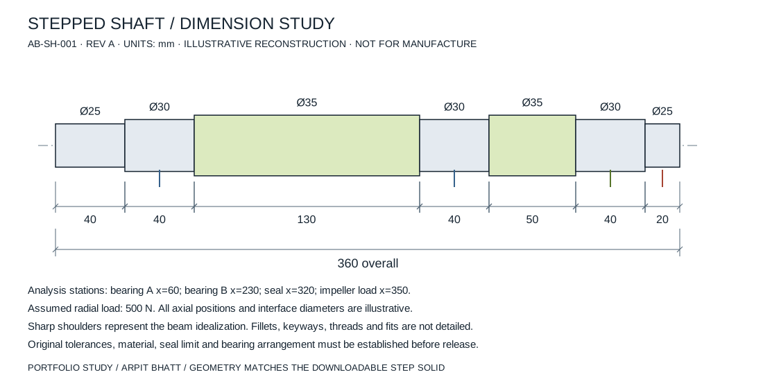
Open the drawing to read all dimensions. Axial dimensions and retained interface sizes are illustrative. This is a dimension study, not a released manufacturing drawing.
| x range (mm) | Length (mm) | Diameter (mm) | Purpose in the example |
|---|---|---|---|
| 0–40 | 40 | 25 | Coupling interface |
| 40–80 | 40 | 30 | Bearing A interface |
| 80–210 | 130 | 35 | Reinforced span |
| 210–250 | 40 | 30 | Bearing B interface |
| 250–300 | 50 | 35 | Reinforced overhang |
| 300–340 | 40 | 30 | Seal interface |
| 340–360 | 20 | 25 | Impeller interface |
1. Power tells us how hard the shaft twists.
One revolution moves through 2π radians. Multiply revolutions per second by 2π to obtain angular speed. Mechanical power is torque multiplied by angular speed, so the torque follows directly:
ω = 2π × 2,900 / 60 = 303.69 rad/s
T = P / ω = 22,000 / 303.69
T = 72.44 N·m = 72,443 N·mm
This is a full-rated-power calculation at the stated speed, not a measurement of actual absorbed pump power. Starting transients, service factors and the operating envelope still need separate consideration.
What the motor does not tell us: 22 kW does not determine the impeller’s radial load. That load depends on hydraulic conditions, geometry and other forces. The 500 N value used next is an explicit example input, not something inferred from the motor rating.
2. Draw the forces before calculating stress.
Treat the bearings as ideal radial supports. There is 170 mm between the two supports and a 120 mm overhang from bearing B to the impeller load. Set upward forces positive.
Take moments about A. Then use vertical force equilibrium:
Rᵦ = 852.94 N
Rₐ + Rᵦ − 500 = 0
Rₐ = −352.94 N
The negative sign is useful information. Bearing A acts downward on the shaft while B acts upward. An overhung load can make a bearing reaction larger than the applied load; the two reactions form the moment balance.
The largest bending-moment magnitude occurs at B:
|Mᵦ| = 60,000 N·mm = 60 N·m
These are radial reactions for one load plane. They do not determine an actual bearing’s life without axial loads, dynamic load ratings, mounting details and the duty cycle.
3. Strength and stiffness ask different questions.
Strength: how much stress does the load create? Stiffness: how far does the component move under that load? A seal can be sensitive to the second question even when the answer to the first looks comfortable.
Start with the cross-section.
In bending, material farther from the neutral axis contributes more strongly to the second moment of area. For a solid circle, I = πd⁴/64. In torsion, J = πd⁴/32. The fourth power is why a modest diameter change has a large effect on section stiffness.
85.3% more section bending stiffness, at the same E
At the outer surface, nominal bending stress is Mc/I and nominal torsional shear is Tc/J, where c = d/2. This gives:
τ = 16T / (πd³)
σᵥ = √(σᵦ² + 3τ²)
For the 35 mm comparison section at M = 60,000 N·mm and T = 72,443 N·mm:
τ = 16 × 72,443 / (π × 35³) = 8.61 MPa
σᵥ = 20.62 MPa
| d (mm) | I (mm⁴) | σᵦ (MPa) | τ (MPa) | σᵥ (MPa) |
|---|---|---|---|---|
| 30 | 39,761 | 22.64 | 13.66 | 32.75 |
| 32 | 51,472 | 18.65 | 11.26 | 26.98 |
| 35 | 73,662 | 14.25 | 8.61 | 20.62 |
In the reconstructed stepped shaft, bearing B remains Ø30 mm—and B is where the bending moment peaks. Its nominal combined stress is still about 32.75 MPa. Enlarging adjacent spans helps deflection; it does not turn every section into a 35 mm shaft.
This comparison uses smooth, solid circular sections. Keyways, shoulders, fillets and surface condition change local stress and fatigue behaviour. The displayed values are not peak FEA stresses or a fatigue assessment.
Theory reference: MIT mechanics notes: bending and torsion. The numerical example and geometry are calculated for this portfolio study.
4. Find the movement where the seal actually sits.
For small elastic deflections, beam curvature is M/(EI). Integrate curvature once to find slope, then again to find deflection. Because this shaft changes diameter, I must change along its length.
y′(x) = ∫ M(x)/[E I(x)] dx + C₁
y(x) = ∫∫ M(x)/[E I(x)] dx dx + C₁x + C₂
Support conditions: y(60) = y(230) = 0
A compact expression for the moment is:
Here ⟨x−a⟩ means max(x−a, 0), with x in millimetres and M in N·mm. Each load contributes only to sections on its right. Use the station table to assign I(x), keep slope and displacement continuous, then determine the two integration constants from the support conditions.
I compared two idealized geometries. In the baseline, the two green spans are Ø30 mm; in the revised model, those same spans are Ø35 mm. Every other diameter and axial station stays fixed.
That is about 28.2% less seal movement in this worked example. At the impeller-load station, the calculated magnitudes change from 0.0875 to 0.0629 mm. The shaft does not gain 85.3% stiffness everywhere: the unchanged seats and the moment distribution still contribute to the complete deflection.
A second method checks the answer.
Apply a virtual unit force at x = 320 mm and find the resulting moment-per-unit-force function m(x). The unit-load method gives the seal displacement magnitude from:
Double integration: 0.0440774 mm
Unit-load check: 0.0440774 mm
The supplied Python calculation uses a 0.01 mm integration spacing and checks that both support displacements are zero. Agreement between these methods checks the implementation of the same beam model. It does not independently validate the assumed loads, bearing stiffness or actual pump geometry.
Is 0.0441 mm acceptable for the real seal? That requires the seal manufacturer’s limits, operating conditions and actual assembly. A smaller number is an improvement in this example, not proof of an acceptable final design.
5. Turn the calculation into a releasable design.
The calculation suggests where stiffness helps. A manufacturing package has to resolve what the simplified model leaves out.
- Confirm the real loads. Establish hydraulic radial force across the operating range, impeller weight, axial thrust and transient torque. Check both bending planes.
- Resolve the interfaces. Confirm bearing seats, fits, shoulder locations, seal running surface, keyways, coupling connection and assembly sequence against the existing components.
- Detail the transitions. Select fillet radii compatible with bearing chamfers and adjoining parts. Assess stress concentration and fatigue at the shoulders and keyways.
- Check the rotating system. Include bearing compliance, critical-speed separation, imbalance and cyclic loading. A material point on a rotating shaft can experience alternating bending stress under a steady transverse load.
- Define inspection and acceptance. Specify material, tolerances, runout, surface finish, seal deflection limits and the test conditions before calling the drawing released.
Project verification included senior-engineer review, checks of critical diameters and runout, and assembled-pump testing without abnormal vibration, seal leakage or bearing heating. The reconstruction shown here is a separate explanation of the mechanics; it is not the original tested component.
What I would carry into the next design.
A constraint is often where the interesting design work begins. Retaining interfaces forces you to think about the load path, where compliance accumulates and which changes create unwanted consequences elsewhere. The best diameter is not simply the largest one. It is the one that meets the actual requirements as part of the whole assembly.
Inspect the files. Follow the calculation.
All files below belong to this illustrative reconstruction. The STEP file is a solid exchange model; it was created with CadQuery, not authored in SolidWorks. It has no native SolidWorks feature tree.
To replace this study with original design evidence, use your approved CAD model, calculation inputs and inspection records. The reconstruction deliberately omits fabrication tolerances and release claims.